The ESP application SECTOR may be used to interactively derive a pieslice cross-section of a galaxy. Before it may be used the NDF image containing the galaxy must be displayed on a suitable display device. This may be done in a manner similar to that described in Session 2. Once the image is displayed, SECTOR may be run.
The first prompt you are faced with asks if you are going to use a cursor to define the position of the galaxy centre and to describe the direction, size and length of the pieslice. If you answer FALSE to this query, you will have to input all your values via the keyboard. However, it is much simpler to use a cursor, as in the example below.
You are then asked on what device the image to be examined is displayed (DEVICE). SECTOR then examines the AGI image database to determine the image's name. This is displayed so that the you can be sure the image used is as expected.% sector ESP SECTOR running. CURSOR - Use the cursor to identify the galaxy centre? /TRUE/ > IMGDEV - Which device is displaying the image /@xwindows/ >
Control then passes to the cursor and you are prompted to use the cursor (and/or the keyboard) to identify the part of the image to be used in the pie-slice cross-section.
The application then asks for information about the image (BACK, SIGMA and, if necessary, PSIZE), how the results are to be displayed (SURF, RADISP, ZEROP) and where the results are to be displayed (SAME, DEVICE).Using /local2/data/esp/ic3374c as the input NDF. Select the centre of the galaxy. Keyboard "2" key: Quit the program. Keyboard "." key: Select the galaxy. Keyboard "1" key: Show the cursor co-ordinates. SKY frame co-ordinates: RA = -11:23:21.7, Dec = 62:13:07 Indicate centre of the outer limit of the sector. Keyboard "2" key: Quit the program. Keyboard "." key: Select centre of the outer limit of the sector. Keyboard "1" key: Show the cursor co-ordinates. SKY frame co-ordinates: RA = -11:23:21.4, Dec = 62:12:25 Select the sector angular width. Keyboard "2" key: Quit the program. Keyboard "." key: Select width of the sector. Keyboard "1" key: Show the cursor co-ordinates. SKY frame co-ordinates: RA = -11:23:23.6, Dec = 62:12:27
The RADISP and SURF options above specify that the `profile' will be displayed in the form of surface brightness versus linear radius. Other options exist for displaying the mean pixel count versus radius transformed into its logarithm, square root or quarter power.MIRROR - Use two diametrically opposite slices? /TRUE/ > TRUE BACK - Background count value /760.5/ > SIGMA - Standard deviation of the background /12/ > Using info from SKY frame - pixels are 0.961 arcseconds square. SURF - Display counts as surface brightness? /TRUE/ > TRUE RADISP - Radius display mode /'r'/ > r ZEROP - Surface brightness zerop point /27.5/ > AUTOL - Automatically search for better origin? /TRUE/ > ARDFIL - Masking ARD file /@ardfile.dat/ > ! !! SUBPAR: Null (!) response to prompt for parameter ARDFIL WARNING! - ARD file not used. SAME - Use the same graphics device for the results graph? /TRUE/ > f DEVICE - Which device/type to display the graph /@x2windows/ >
AUTOL set to TRUE means that the application will look at the parts of the image immediately surrounding the galaxy centre suggested and, if possible, will identify a better candidate. In the instance given AUTOL has been used.
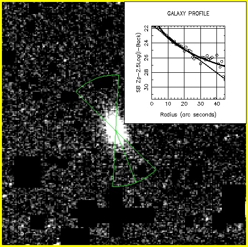
The option MIRROR allows for the pieslice defined to be duplicated on the other side of the galaxy origin. This effectively increases the signal since more of the image will be sampled, but is only really applicable when the image is roughly symmetrical. Figure 4 shows the selected sector displayed on the galaxy. It also shows the mirror image sector generated by the MIRROR parameter being set to TRUE.
The graph is then displayed and you are asked to indicate (using the cursor) the radius range of the profile points to be used to calculate the scale lengths.
The graph then displays the galaxy profile `fits' and the results of the scale length calculations are printed, showing values for the central surface brightness of the galaxy for both elliptical and spiral galaxy models.Select a point defining the lower radius limit. Keyboard "2" key: Quit the program. Keyboard "." key: Select lower radius limit. Select a point defining the upper radius limit. Keyboard "2" key: Quit the program. Keyboard "." key: Select upper radius limit.
Finally, you are given the chance to obtain a pieslice of some other part of the image.SECTOR Results for file: /local2/data/esp/ic3374c Origin: -11:23:21.6 62:13:08 Pixel count (raw): 980.00 Pixel count (subtracted): 219.50 Pixel count (sigma): 18.29 Pixel count (Log(I-BACK)): 2.34 Mag. rel. zero point: 21.6464 Central mag. spiral: 21.4506 Central mag. ellipt: 16.9384 Above or below sky: -0.5397 Number of data points: 46 ie. 43.22" Range used (arc sec): 0.63, 26.88 Points used for spiral calculation: 27 Scale length spiral: 6.2582 Points used for elliptical calculation.: 27 Scale length elliptical: 0.08769
OUT - Text file for profile output /@sectout.dat/ >
AGAIN - Profile again? /FALSE/ >
ESP --- Extended Surface Photometry